自动补偿-可选操作第3步和第4步
如果要调节参数和额外溢出目标,请参照以下步骤:
一旦您完成自动补偿设置中的第2步之后您可以直接跳到第5步进行矩阵计算,或者您也可以进行第3步和/或第4步操作。本教程将通过介绍第3步和第4步在内的方法介绍如何简单进行补偿设置。如果您对在FCS Express中如何进行自动补偿设置还不太熟悉,请在Automatic Compensation(自动调节补偿)章节完成Automatic Compensation(自动调节补偿)。
| • | 第3步-调节参数(可选操作)允许用户利用自己单染对照设门进行计算,而不是自动补偿中默认的标记门。 |
| o | Adjust parameters(调节参数))对于将进行计算补偿的群体的改善很有用。例如,如果Automatic Compensation Setup(自动调节补偿设置)没有对群体进行一个很好的评估或者您想从其他文件、门或者绘图中使用一个群体,步骤3的用处就凸显出来了。在Stained(染色)和Unstained(未染色)列,拖放一个绘图或者门到参数中,参数将被整体调节或改变。如果一个门被拖拽,补偿定义将根据其起源的门和绘图来进行(当要使用一个门时,请记住您定义的门的层次)。如果一个绘图被拖拽,补偿定义将根据您拖拽的绘图来计算,该绘图的门不改变。在这一部分,拖放新的绘图、文件或者门将跳过自动设置步骤,使用您选择的门和绘图进行后续操作。 |
| • | 第4步-增加额外的溢出目标(可选操作) 将允许用户在没有定义一个源荧光情况下,增加其他的荧光目标定义。 |
| o | Adding extra spillover targets(增加额外的溢出目标)对于用户了解在以后的实验中,如果增加了额外的参数,溢出的数据如何很有用。如果要增加额外的溢出目标,只需点击您想要增加的额外目标的框即可。注意:注:只有获得了数据的参数才能才能出现额外溢出目标。 |
在这一教程中,AutoCompAdditionalSteps.fey版面将会被使用,这一版面可在Tutorial Sample Data archive(教程样本数据文档)中被找到。在这一版面中,已经使用标准的默认设置创建了一个自动补偿设置定义(命名为New Automatic Compensation),这在之前的章节中已经完成了。这一版面包括4页,展示如下:
| • | Gating Strategy and Sample (设门技术和样本)页:该页上的Gate View(查看门)展示了设门技术(通过补偿设置自动创建,显示为紫色)和我们将要使用的门(红色和蓝色门)。这些绘图已被从左上方进行排序,用以显示应用的是怎样的设门层次。每个绘图之后的绿色箭头展示的是这些门是如何被应用和定义的。带有SAMPLE COMPENSATION (样本补偿)标签的绘图是应用了自动补偿设置定义(命名为New Automatic Compensation),的。该页右边的绘图已带有Data for New Compensation Gates(新补偿门的数据)标签,但没应用任何补偿。此Data for New Compensation Gates(新补偿门的数据)绘图 上有PE positive(PE阳性)、PerCPCy5-5 positive(PerCPCy5-5阳性)和阴性群体门。这些门将在后面的调节参数步骤中使用。 |
| • | 位于左边的Scatter Plot(散点图)页:该页是通过Automatic Compensation Setup(自动补偿设置)工具创建的,展示了用来计算补偿矩阵的染色和未染色群体。 |
| • | CD 62L YG PE-A control页:该页是通过Automatic Compensation Setup(自动补偿设置)工具创建的,展示了被用于计算PE参数补偿溢出的当前门。 |
| • | CD4 PerCP-Cy5-5-A对照页:该页是通过Automatic Compensation Setup(自动补偿设置)工具创建的,展示了用来计算PerCPCy5-5参数的补偿矩阵的染色和未染色群体。 |
在接下来的步骤,我们将:
| • | 调节参数,用以为单染和未染对照定义新的门。 |
| • | 改变设门的层次,让散点图(通过自动补偿设置定义的)变为手动定义门的下级。 |
| • | 增加一个额外溢出目标,用以查看另一个目标的潜在溢出。 |
| 1. | 选择File(文件)标签→Open(打开)(图T3.1)。 |
| 2. | 打开版面教程样本数据库中的AutoCompAdditionalSteps.fey(用户可在之前的内容中查看对该版面的描述)。 |
| 3. | 点击Created manually(手动创建)文件夹→New Automatic Compensation(新自动补偿)→Automatic Compensation Setup(自动调节补偿设置),这些可以在补偿导航器中找到(图T8.22红框显示)。 |
| 4. | 在Automatic Compensation Setup(自动补偿设置中) |
| 5. | 点击Data List(数据列表)标签(图T8.8)。 |
| 6. | 在数据列表中选择所示的文件(图T8.8): |
| • | Specimen_001_PE_CD62L.fcs |
| • | Specimen_001_PerCP Cy5-5 CD4.fcs |
| • | Specimen_001_PE_unstained.fcs |
| 7. | 根据下表选择每个数据文件的参数: |
Data File(数据文件) |
Parameter(参数) |
Specimen_001_PE_CD62L.fcs |
9 - YG PE-A |
Specimen_001_PerCP Cy5-5 CD4.fcs |
10 - PerCP-Cy5-5-A |
Specimen_001_PE_unstained.fcs |
Universal Negative(通用阴性) |
| 8. | 点击第2步-构建柱状图来使构建直方图窗口展开(图T8.13)。 |
| 9. | 点击Build Histograms(构建柱状图)按钮(图T8.13)。 |
| 10. | 一个要求删除先前创建的layout页面和门的窗口就打开了。点击Yes。 |
如前面的教程一节,我们现在将对Scatter Gate(散点图门)进行一些调整,以改进自动标记/门的单染和阴性群。
在这一实例中,对于定义的散点图,FSC-H vs FSC-A并不是正确的参数,所以我们将用Scatter Gate(散点图门)代替Scatter Gate(散点图门)。
| 11. | 请选择Scatter Plot(散点图)页并改变显示散点图的X-轴的参数为SSC-H。 |
| 12. | 选择Gating(门操作)标签→Create Gates(创建门)→Rectangle(矩形门)。 |
| 13. | 如图T8.22(左面板)所示,在细胞群体周围画一个门。 |
| 14. | 在出现的Create New Gate (创建新门)对话框,选择Replace an existing gate(替代一已有的门)的按钮并且选择位于下拉菜单底部的Scatter Gate(散点图门)(图 T8.22a, 右版面). |
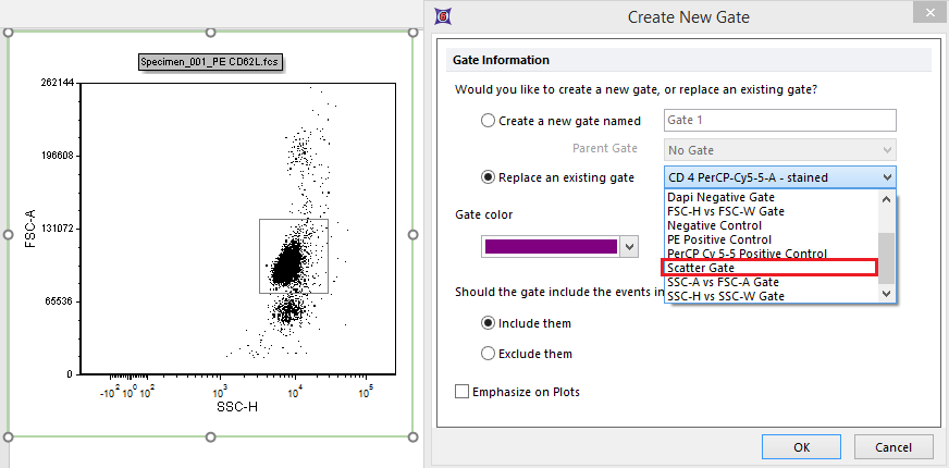
Figure 8.22a - A new Scatter Gate is drawn and used as replacement for the original one.
| 15. | 点击OK。 |
注意:原始的散点图门已被用户定义的新门取代。对于取代原始的散点图门,这一操作很方便,因为版面中所有的单染对照柱状图都已经使用该门。如果我们已经创建了一个新门,那我们就必须将该门应用到单染对照柱状图。注意:之后的单染对照柱状图页面也将随着新门更新。
在该版面(包括单染对照柱状图的版面)后面的页面中,用户可决定标识的位置。
| 16. | 点击第3步-调节参数(可选操作)(图 T8.22b) |
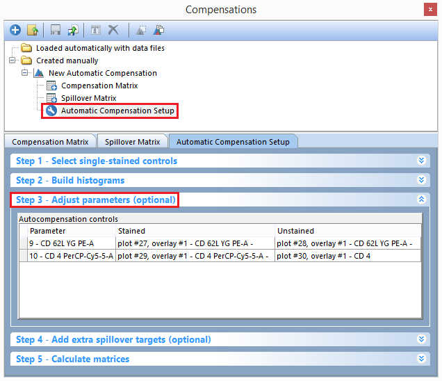
Figure T8.22b - Selecting the Automatic Compensation setup and Step 3 for the New Automatic Compensation definition.
我们现在将用手动定义的门代替自动补偿设置中定义的门。手动定义的门呈现如下:
| • | 一个带有FSC和SSC参数及Dapi阴性门的设门层次已经被定义。这一层次用来排除碎片和其他不需要的事件。 |
| • | Negative Control(阴性对照)门:该门是Dapi Negative Gate(Dapi阴性门)层级的子门。它定义的是一个阴性或者未染色的对照群体。 |
| • | PE Positive Control(PE阳性对照)gate: This gate is a child of theDapi Negative Gate(Dapi阴性门)层级的子门。它定义的是PE单色对照群体。 |
| • | PerCP CY5-5 Positive Controlgate: This gate is a child of theDapi Negative Gate(Dapi阴性门)层级的子门。它定义的是PerCP CY5-5单色群体。 |
| 17. | 在gate view(查看门)中点击Negative Control(阴性对照)门,并按住鼠标左键不放(图T8.23)。 |
| 18. | 拖拽Negative Control(阴性对照)门到Unstained(未染色)列CD62L YG PE-A行处,然后松开鼠标左键。 |
| 19. | 在gate view(查看门)中点击Negative Control gate(阴性对照门)选项。 |
| 20. | 拖拽Negative Control gate(阴性对照门)到Unstained(未染色)列CD4 PerCP-Cy5-5-A行处,然后松开鼠标左键。 |
Figure T8.23 - Dragging the Negative Control gate from the gate view to the Unstained column for both parameters.
现在第3步-调节参数(可选操作)部分将如图T823b所示。
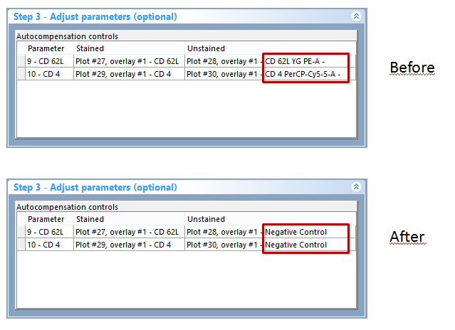
Figure T8.23b The Step3 section after the drag&drop
我们之前拖放了Gate View(查看门)中的Negative Control(阴性对照门)。我们现在将使用一个绘图作为来源进行拖拽(图T8.24)。
| 21. | 在Data for New Compensation Gates plot(新补偿门绘图数据)(位于页面的右边)中点击PE Positive Control(PE阳性对照)门,并按住鼠标左键不放。 |
| 22. | 将其拖拽到Stained(染色)列CD62L YG PE-A行处,然后松开鼠标左键。 |
| 23. | 在Data for New Compensation Gates plot(新补偿门绘图数据)(位于页面的右边)中点击PerCPCY5-5 Positive Control(PerCPCY5-5 阳性对照)门,按住左键不放(图T8.24)。 |
| 24. | 将其拖拽到Stained(染色)列CD4 PerCP-Cy5-5-A行处,然后松开鼠标左键。 |
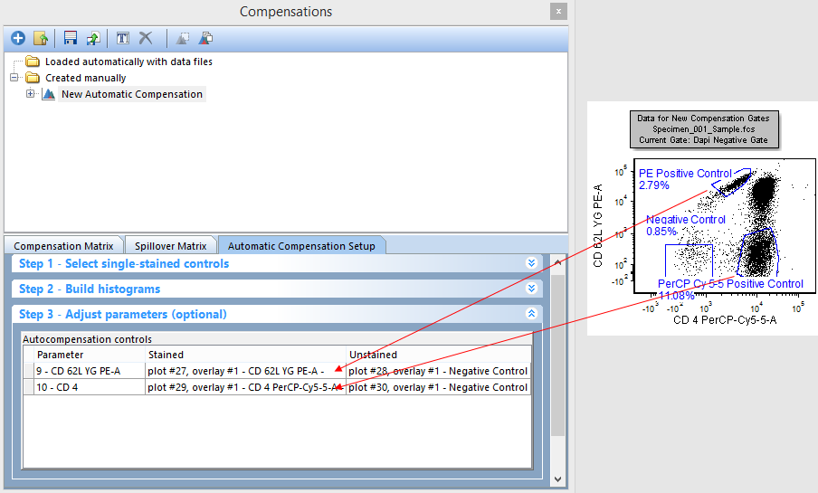
Figure T8.24 - Dragging and dropping gates from a plot to the Stained column in step 3 for each parameter.
第3步-调节参数(可选操作)将如下图T8.25所示,当你完成以上步骤后。
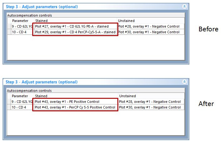
Figure T8.25 - Step 3 - Adjust parameters (optional) after dragging and dropping gates from the gate view and plots onto the stained and unstained population columns.
| 25. | 现在点击步骤5-计算矩阵。 |
| 26. | 点击Calculate matrices (矩阵计算)按钮。 |
注意:针对New Automatic Compensation(新的自动补偿)定义的溢出矩阵已经变为(见下图T8.26)反映改变后的新的设门。用这种方式,用户可拖拽任何门或者全部绘图到Stained(染色)和Unstained(未染色)列,用以定制用户自己的Automatic Compensation Setup(自动补偿设置)。
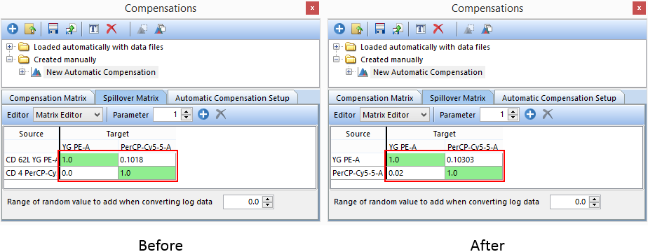
Figure T8.26 - The original Automatic Compensation Setup definition (left) compared to the Automatic Compensation Setup definition (right) that is based on a gating hierarchy and manually defined positive and negative controls.
另一个有用的窍门是将散点图门和其子门(通过自动补偿设置创建)变为另一个用户已定义的门的子门。下面步骤中,我们将加把散点图门变为Dapi Negative(Dapi阴性)门的子门。当这一矩阵被重新计算后,用于碎片排除的手动输入设门层次将随着Automatic Compensation Setup(自动补偿设置)被考虑在内。如果我们要重置补偿的变化,首先我们要将此版面关闭,然后再重新打开。
| 27. | 选择File(文件)标签→Close(关闭)。。(不要保存任何改变) |
| 28. | 选择File(文件)标签→Open(打开)。 |
| 29. | 打开教程样本数据库中的AutoCompAdditionalSteps.fey版面文件。 |
| 30. | 点击Created manually(手动创建)文件夹。→New Automatic Compensation(新自动补偿)→Automatic Compensation Setup(自动调节补偿设置),这些可以在补偿导航器中找到(图T8.22红框显示)。 |
| 31. | 在Automatic Compensation Setup(自动补偿设置中) |
| 32. | 点击Data List(数据列表)标签(图T8.8)。 |
| 33. | 在数据列表中选择所示的文件(图T8.8): |
| • | Specimen_001_PE_CD62L.fcs |
| • | Specimen_001_PerCP Cy5-5 CD4.fcs |
| • | Specimen_001_PE_unstained.fcs点击并按住Gate View(门视图)中的Scatter Gate(散点图门)。 |
| 33. | 根据下表选择每个数据文件的参数: |
Data File(数据文件) |
Parameter(参数) |
Specimen_001_PE_CD62L.fcs |
9 - YG PE-A |
Specimen_001_PerCP Cy5-5 CD4.fcs |
10 - PerCP-Cy5-5-A |
Specimen_001_PE_unstained.fcs |
Universal Negative(通用阴性) |
| 34. | 拖拽Scatter Gate(散点图)到Dapi Negative Gate(Dapi 阴性门)上方松开鼠标(图T8.27)。 |
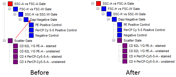
Figure T8.27 - Dragging and dropping the Scatter Gate onto the Dapi Negative Gate to create a new gating hierarchy
点击步骤5-计算矩阵。
35.点击第2步-构建柱状图来使构建直方图窗口展开(图T8.13)。
36.点击Build Histograms(构建柱状图)按钮(图T8.13)。
37.一个要求删除先前创建的layout页面和门的窗口就打开了。点击Yes。
38.点击Calculate matrices (矩阵计算)按钮。
注意:针对New Automatic Compensation(新的自动补偿)定义的溢出矩阵已经变为(见下图T8.26)反映改变后的新的设门。这是因为通过Automatic Compensation Setup(自动补偿设门)创建的绘图来自Scatter Gate(散点图),所以通过在设门层次中移动Scatter Gate(散点图),这些绘图的统计数据将会自动更新。
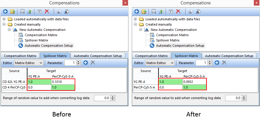
Figure T8.28 - The original Automatic Compensation Setup definition (left) compared to the Automatic Compensation Setup definition (right) that is based on the new gating hierarchy of the Scatter Gate.
现在我们将使用第4步-增加额外的溢出目标(可选操作)来决定FITC参数的理论溢出值。
39.点击第4步-增加额外的溢出目标(可选操作),将这一窗口展开。
40.选中FITC-A复选框(图T8.28)。
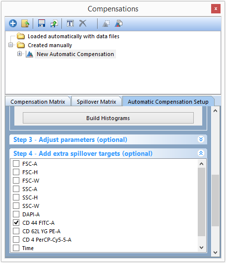
Figure T8.28 - Adding an extra spillover target in Step 4.
41. 点击Calculate matrices (矩阵计算)按钮这个按钮在步骤5-计算矩阵中。
此Spillover Matrix(溢出矩阵)标签将展示你在第4步-增加额外的溢出目标(可选操作)用选中的和FITC-A参数一起的原始参数(图T8.29)。在该矩阵中,FITC-A列展示了该参数与其他参数间的理论补偿。
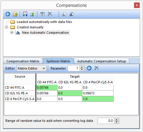
Figure T8.29 - The compensation matrix displaying the extra spillover target that was added. The compensation values for CD 44 FITC-A vs other sources/targets is the theoretical value.
这引导我们来到Automatic Compensation Optional(自动补偿选项)第3步和第4步的最后。请参见手动调节补偿教程教程或者Compensation (补偿)教程的手动调节部分。
