Well Gates

Contents
Well gates are gates that include one or more wells from a plate heat map. A Well gate can include either contiguous and/or non contiguous wells.
There are two ways of creating well gates:
1.Creating a single well gate that includes one or multiple wells of interest (either contiguous and/or non contiguous).
2.Create multiple well gates, one for each of the selected well of interest (either contiguous and/or non contiguous).
The initial steps to create a Well gate are common to both scenarios above:
1.Select the Gating tab→Create Gates→Well command. (Alternatively, right-click on the plate heat map and choose Create gate→Well).
2.Click anywhere on the plate heat map (alternatively, click-drag the mouse around multiple wells/clusters or around all the wells/clusters) (Figure 5.87).
•An Editing New Well Gate dialog (with instructions) for the well gate will appear above the plate heat map.
•A Create New Gate dialog for the well gate will appear on the screen (Please note that by default the Gate Properties section of the dialog is collapsed).

Figure 5.87 Setting a Well Gate. Please note that in thsi screenshoit the "Gate Properties" section of the "Create New Gate" dialog has been expanded.
3.The Create New Gate dialog appears and allows users to create a single Well gate, multiple individual Well gates and also to replace an existing Well gate.
Create a new gate named |
The option allows users to create a single well gate that includes one or multiple wells of interest (either contiguous and/or non contiguous). The new gate will be a child of the Overlay Gate of the base overlay on the plot. To create the new gate as a child of a specific gate in the hierarchy, choose the parental gate in the hierarchy from the Parent Gate drop-down (see below). The hierarchy of your gates can be adjusted at any time within the Gate View object as well.
|
Create Individual gates for each well |
The option allows users to create multiple well gates, one for each of the selected well of interest (either contiguous and/or non contiguous). The new gates will be a child of the Overlay Gate of the base overlay on the plot. To create the new gate as a child of a specific gate in the hierarchy, choose the parental gate in the hierarchy from the Parent Gate drop-down (see below). The hierarchy of your gates can be adjusted at any time within the Gate View object as well.
Creating individual gates for each well (or all the wells) is especially useful when many wells must be gated individually. The functionality can be used for Heatmaps displaying data from a multi-well plate and also when the Heatmap displays cluster assignments from clustering algorithms.
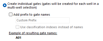
When the option is selected, the user can customize the gate names by Adding a prefix to the gate name.
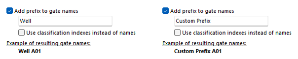
By default, the prefix is "Well" when the Heatmap displays wells from a multiwell plate (as in the example pictures below; left pane), or a short text describing the transformation plotted into the Heatmap (e.g. the classification description is "KMeans Cluster Assignment" in case the Heatmap displays a KMeans clustering). The prefix may be customized by the user at their convenience (pictures below; right pane).
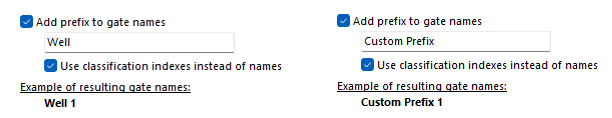
If the prefix check box is checked, the name of the well (e.g. A01) may be replaced by an integer index (e.g. 1; see the screenshot below) by selecting the Use classification indexes instead of names check box.
When multiple individual Well gates are created, user may also want to color the individual gates with different colors so they can more easily discriminated via backgating. Users may click on the Gate color drop-down menu, and by select Use unique gate colors (Figure 5.88) to automatically create different gate colors for each automatic well gate created.
 Figure 5.88 The "Create New Gate" dialog with the "Use unique gate colors" button highlighted.
|
Replace an existing gate |
To replace an existing gate with the newly created gate, select the Replace an existing gate radio button and choose the gate you wish to replace from the drop-down list. The new gate will replace the old gate without affecting your gating hierarchy. Please see below for more details. |
Gate Color |
Select the preferred color from the drop down menu.
Note: When Individual Well Gates are created, unique gate colors can be used (see above). |
Parent Gate |
When a new gate is created, the new gate will be a child of the Overlay Gate of the base overlay on the plot. The Parent Gate option allows to modify this choice and thus make the new gate a child of a different gate.
Note: when an existing gate is replaced, the parent gate of the drawn gate will be the same parent gate of the replaced gate.
|
Emphasize events on Color Dot plots |
See the Creating Gates chapter for more details. |
Always create a Data Specific Gate when moving this gate |
See the Creating Gates chapter for more details. |
Exclude events inside this shape |
See the Creating Gates chapter for more details. |
3.Once the Create New Gate dialog is completed, click OK to create the Well gate and close the Create New Gate dialog.
The following steps vary based on which option has been selected in Step 3:
•Unique Well gate (or Replace an existing gate)
•Multiple individual Well gates
Unique Well gate (or Replace an existing gate)
If a unique Well gate has been created in Step 3 above (or the Replace an existing gate has been selected), the well selected in Step 2 above will be highlighted on the Heat Map and the Editing New Well Gate dialog, will allow to modify the selection at the user convenience. This means that wells can be further added or removed to the selection. This can be done by holding the Ctrl key while clicking on individual wells of interest (or while dragging a rectangle across a group of wells of interest).
In Figure 5.89 below, the well gate obtained by selecting wells from A02 to A05, as a unique Well gate named Gate 1 is depicted. Well selection can be edited when the Editing New Well Gate dialog is visible. When the selection is completed, click Close.
")
Figure 5.89 - Well Gate. Four wells are outlined in red (A02, A03, A04 and A05)
Multiple individual Well gates
If multiple individual Well gates have been created in Step 3 above, the Editing New Well Gate dialog closes together with the Editing New Well Gate dialog. Well gates will not be shown in the Heat Map (but may be shown by right clicking on the Heatmap and by selecting Show gates). In the example below (Figure 5.90), multiple individual Well gates have been created after selecting wells from A02 to A05. The same red color has been selected for all individual Well gates in this example.

Figure 5.90 - Example of multiple individual Well gates.
Replacing an existing gate
To replace an existing Well gate, simply draw a new Well gate and, in the Create New Gate dialog, select the gate that has to be replaced from the "Replace an existing gate" (Figure 5.91 below). After clicking OK, the Editing New Well Gate will open and will allow you to modify the selection. Please see the Unique Well gate (or Replace an existing gate) section above.

Figure 5.91 - The Create New Gate dialog with the "Reaplce an existing gate" option selected.
Editing an existing gate
To activate (and modify) an existing Well gate, right-click on the Plate Heat Map, select Edit gate, and choose the gate to activate from the sub-menu (Figure 5.92 below). Please see the Unique Well gate (or Replace an existing gate) section above.

Figure 5.92 - The Edit Gate option in teh right click menu.