The Compensation and Unmixing Window
To create, remove, and manage Compensation and Unmixing definitions open the Compensation and Unmixing window by selecting the Tools tab→Transformations→Compensation and Unmixing command (Figure 9.5).

Figure 9.5 The Tools tab.
A dockable window titled Compensations and Unmixing will open. This window lists all of the compensation definitions and all the Unmixing definitions that are available in the layout within the Loaded automatically with data files or the Created manually folders (Figure 9.6).
•The Loaded automatically with data files folder shows definitions that were automatically loaded with a data file presently showing on the layout (e.g., a compensation definition defined during acquisition and saved as metadata with a modern FCS 3.0 or greater format .fcs data file).
•The Created manually folder shows definitions (either compensation or unmixing definitions) that have been created manually within FCS Express.
Jump to:
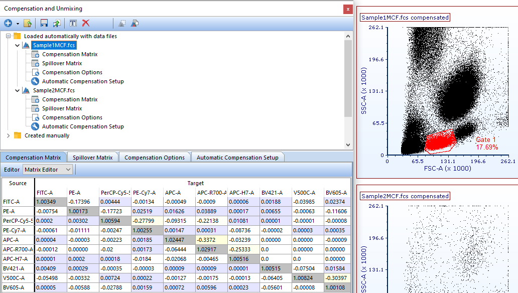
Figure 9.6 Compensations dialog showing compensations available in the layout.
The Compensations and Unmixing window (Figure 9.7) is dockable and pinnable like many other windows in FCS Express. There are many actions you can perform from the Compensations and Unmixing window tool bar. You can perform the action either by pressing the appropriate button (hover the mouse over the button for tooltip) or by right-clicking on a definition folder or sub-item. The actions are summarized in the table below:
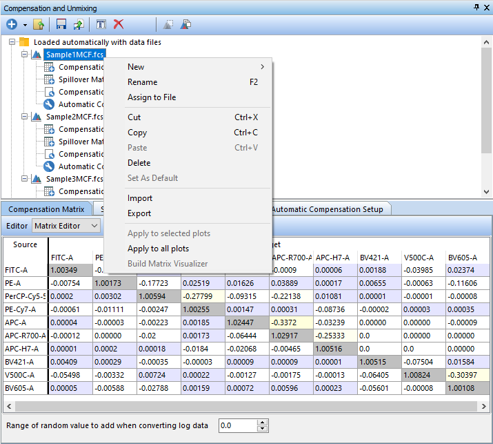
Figure 9.7 Compensations dialog showing available commands and actions.
Action |
Command |
Explanation |
Create a new definition (either a compensation or an unmixing definition) |
|
Add a new compensation/unmixing definition. |
Import a definition from a file |
|
Import a previously saved definition (*.compensation or *.unmixing) file. |
Export the selected defintion |
|
Export a compensation (*.compensation) or an unmixing (*.unmixing) definition file for use in other layouts. |
Assign this Compensation/Unmixing to a data file |
|
Assign a definition to a file or series of files. |
Rename the selected definition |
|
Renames the selected compensation definition. |
Delete |
|
Deletes a compensation definition from the compensation window and the plots to which it was applied. |
Cut definition |
Right-click on a definition → Cut |
Performs a cut command on the compensation definition. If performed on the Compensation or Spillover Matrix, the Matrix can be pasted into a Text Box or other document. |
Copy definition |
Right-click on a definition → Copy |
Performs a copy command on the compensation definition. If performed on the Compensation or Spillover Matrix, the Matrix can be pasted into a Text Box or other document. |
Paste definition |
Right-click on a definition → Paste |
|
Set as Default |
Right-click on a definition → Set as Default |
Sets the selected compensation definition as the default compensation. The default compensation is the one that will be used when adding new plots. Only Created manually compensation definitions may be Set as Default; however, compensation definitions Loaded automatically with data files may be copied into the Created manually category for this purpose. |
If a Compensation definition is selected, the Compensations and Unmixing window will display four tabs (Figure 9.8):
•Compensation Matrix
•Spillover Matrix
The Compensation Matrix and Spillover Matrix tabs allow you to view and Manually Edit a Compensation Definition. The Compensation Options tab allows you to chose how compensation is applied to the current layout and whether to append or overwrite compensated parameters. The Automatic Compensation Setup allows you to calculate a new matrix using single stained controls.
For both the Compensation Matrix and the Spillover Matrix you can choose to view the Matrix Editor or List Editor from the Editor drop-down (Figure below) to view a matrix of Source vs. Target (Figure below and left) or to view a list of Target - % Source (Figure below and right).

Figure 9.8 Compensations dialog showing available tabs. Matrix Editor View (left) and List Editor View (right).
A quality control for your compensation definitions may also be run by using the Multiplot commands from the Plot tab→Multi Plot→NxN Plots Compensated feature which will create multiple plots that display combinations of all parameters versus each other of the parameters involved in the compensation matrix of the parent plot (Figure 9.9).
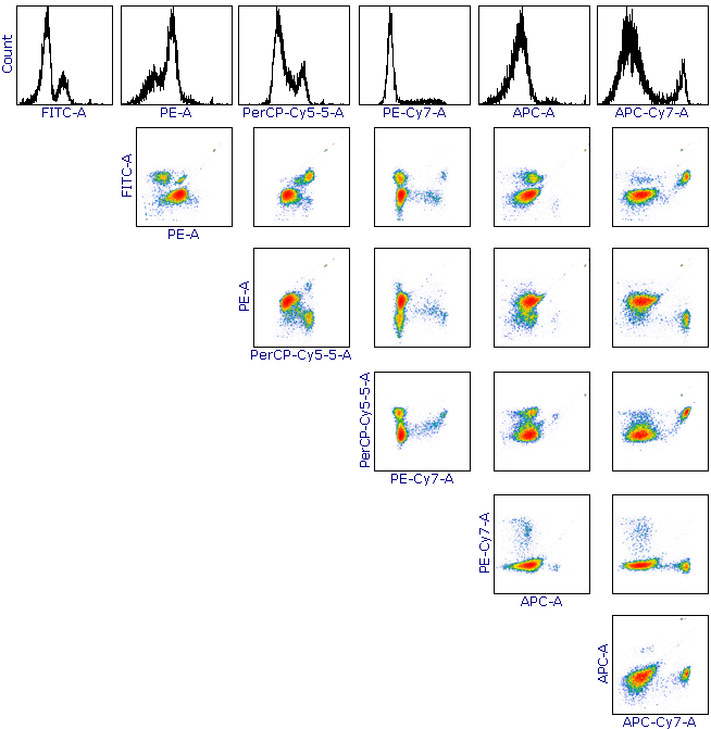
Figure 9.9. NxN Plots Compensated.
If an Unmixing definition is selected, the Compensations and Unmixing window will display three tabs:
•Unmixming Matrix (Figure 9.10)
•Options (Figure 9.11)
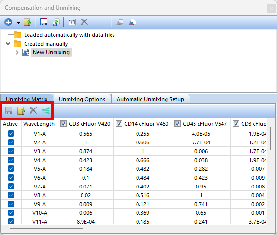
Figure 9.10.The Unmixing Matrix tab in the Compensation and Unmixing dialog.
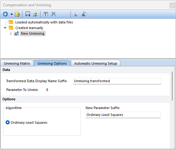
Figure 9.11.The Unmixing Options tab in the Compensation and Unmixing dialog.
•The Unmixing Matrix tab shows the Endmembers of the Unmixing definition and allows you to enable/disable specific detectors/Endmembers by checking and unchecking the boxes associated with detectors/Endmember.
oIcons for Save, Load, and Delete (red highlighting in figure above) will allow you to save, load, and delete selected endmembers in the table.
oThe icon for EasyPanel (red highlighting in figure above) allows to upload the Unmixing Definition to EasyPanel.
oThe endmembers in the Unmixing Matrix can be renamed by right clicking on the endmember and selecting Rename. (Figure 9.12 (below)).
oPlease see our section on Creating or Modifying an Unmixing Definition for additional details.
•The Options tab displays the Algorithm used to calculate the Unmixing Definition and the parameter that has been unmixed (please refer to Step 3 of the Automatic Unmixing Setup).
oThe New Parameter Suffix edit box will allow you to change or remove the suffix applied to parameters created by unmixing.
•The Automatic Unmixing Setup tab allows you to add, edit, and display the steps performed in the automatic unmixing.
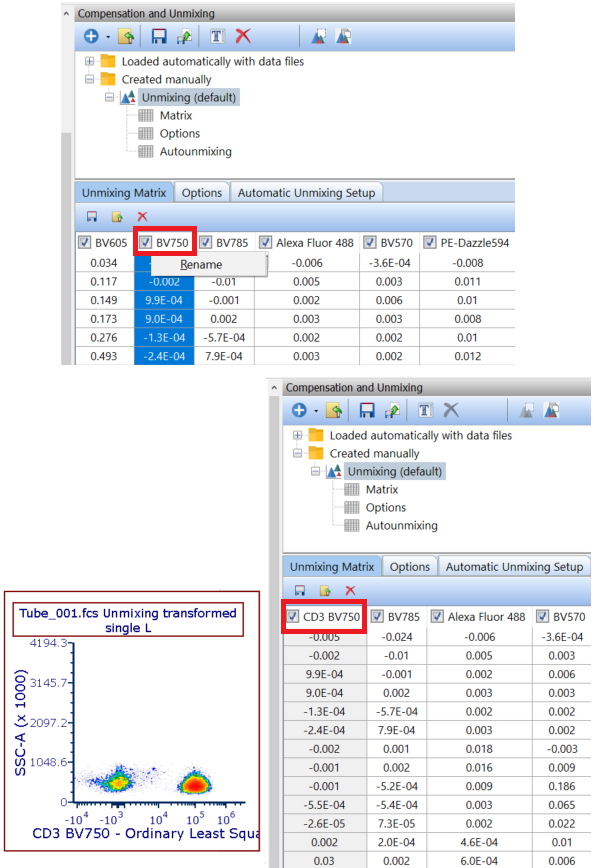
(Figure 9.12) Renaming the endmember in the Unmixing Matrix. The BV750 endmember (top red highlighting) was renamed to CD3 BV750 (bottom) Plots will update changes and reflect the new endmember on the axis.
Visualized Matrix
FCS Express has the capability to add a Visualized Matrix page on the layout (Figure 9.13). The Visualized Matrix page depicts a chart displaying the Detector vs Intensity for each single stained control added in the wizard, as well as a spreadsheet with the charted values (each detector is labeled by Detector # and Wavelength). Learn more about using a Visualized Matrix.

Figure 9.13 Visualized Matrix page automatically created upon completion of the Automatic Unmixing Setup.
