Creating an Unmixing Definition Using Single Stained Controls
FCS Express can calculate the entire Unmixing definition for you.
To get started, use the Tools tab→Transformations→Compensations and Unmixing command to open the Compensations and Unmixing window. Then add a new Unmixing definition using the down arrow button next to the Add button ![]() (Figure 9.34).
(Figure 9.34).
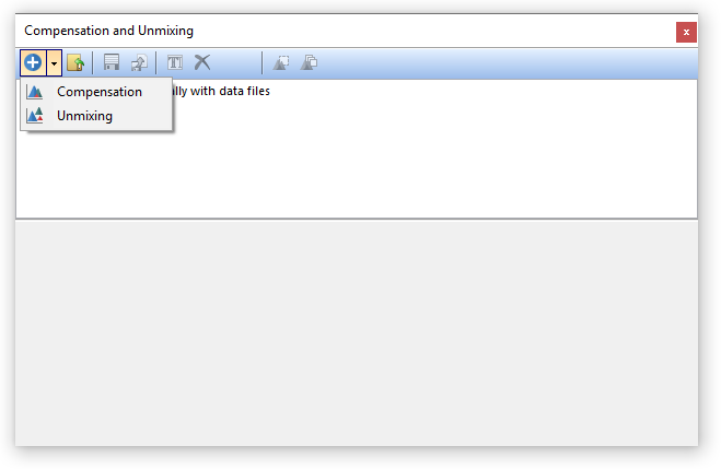
Figure 9.34 Adding a new Unmixing definition.
The bottom pane of the Compensation and Unmixing window will automatically display the Automatic Unmixing Setup tab. The Automatic Unmixing Setup tab contains 6 steps to calculate your Unmixing matrix. Step 5 is optional and does not have to be completed to generate an unmixing definition (Figure 9.35).
•The Automatic Unmixing Setup settings are saved with the layout. To create another unmixing matrix from a different set of data, simply add a new Unmixing definition using the down arrow next to Add ![]() and begin the Automatic Unmixing Setup process again or create a new layout.
and begin the Automatic Unmixing Setup process again or create a new layout.
We also suggest that you export the unmixing definition determined in the Automatic Unmixing Setup and load/apply it to different layouts and files rather than re-creating the same unmixing definition many times. Please see the section on Using Definitions to determine the best way to apply your unmixing to your sample data sets.
•The Options tab contains a New Parameter Suffix edit box which is defaulted to Ordinary Least Squares. If you would like your newly created unmixed parameters to use a different suffix, the default may be edited to your desired text, or removed entirely.
•The Unmixing Matrix tab will contain your unmixing matrix once the wizard is completed or will display an imported matrix.
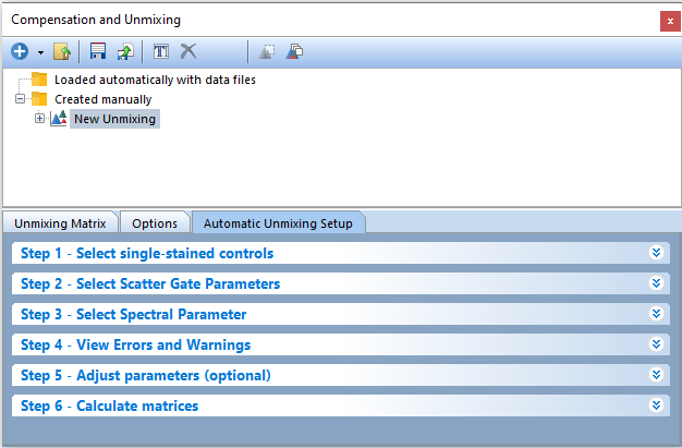
Figure 9.35 The Automatic Unmixing Setup tab.
•Step 1 - Select single-stained controls
In order to automatically calculate an Unmixing definition, you will need to provide the software with a reference spectrum for each dye you wish to unmix. The reference spectrum for a dye is calculated by subtracting a negative spectrum (i.e. the spectrum of an unstained population) from a positive spectrum (i.e. the spectrum of a stained population for that dye of interest).
The negative spectrum can derive either from an internal negative (i.e. an unstained population present together with the positive population within the same file) or from an external negative (i.e. an unstained population in a different file). FCS Express is flexible with which controls you may use and allows you to deal with either scenario.
Different external negative controls may also be use. This is useful when single stained control(s) are derived from different media (different cells types, beads, etc...). FCS Express allows you to define multiple negative controls and thus subtract the appropriate negative control from each positive control.
Autofluorescence extraction
Autofluorescence can be unmixed just as any other actual dye. To unmix autoflouorescence, simply add a sample containing the population on which you want to calculate the autofluorescence and select Autofluorescence control from the Sample Type dropdown and set the Negative control column to No negative. Some useful case scenarios are depicted below:
Single Stained Controls using an internal negative population - Figure 9.36
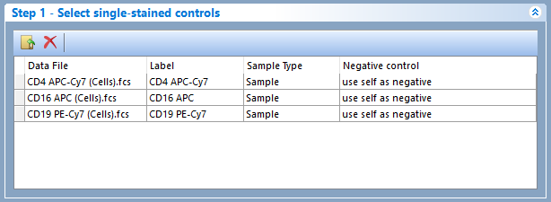
Figure 9.36 - In this case scenario, all single stained controls use an internal negative population as negative control.
Single Stained Controls using an external negative population - Figure 937
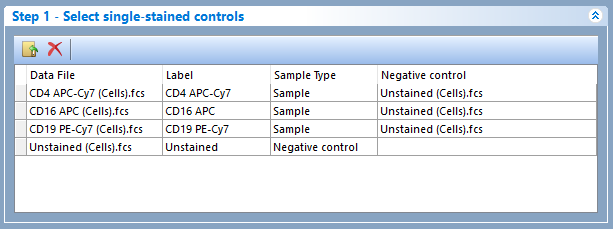
Figure 9.37 - In this case scenario, all single stained controls use an external negative population (i.e. a population in another FCS file) as negative control.
Single Stained Controls using multiple external negative populations - Figure 938
TIP: When multiple negative controls are required, customizing their label (see "Label" column in the screenshot below), will facilitate their selection in the "Negative control" column of Step 1.

Figure 9.38 - In this case scenario, all single stained controls use a specific external negative population (i.e. a lymph population in another FCS file) as negative control. The Label column can be modified to distinguish each population.
Single Stained Controls using a mix of internal and external negative population - Figure 9.39
TIP: When multiple negative controls are required, customizing their label (see "Label" column in the screenshot below), will facilitate their selection in the "Negative control" column of Step 1.
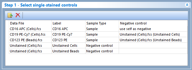
Figure 9.39 - In this case scenario the APC dye uses an internal negative control, the PE-Cy7 dye uses an external negative control from the "Unstained (Cells).fcs" file, and the PE dye uses an external negative control from the "Unstained (Beads).fcs" file.
Note: Although the label for both the "Unstained (Cells).fcs and the "Unstained (Beads).fcs" files was "Unstained" by default, the label has been manually customized to "Unstained cells and" and "Unstained beads" instead.
Autofluorescence Extraction with Single Stained Controls using a mix of internal and external negative population - Figure 9.40

Figure 9.40 - In this scenario both the PE-Cy7 and APC dyes use an external negative control from the "Unstained (Cells).fcs" file. The PE dye uses an internal negative control.
Autofluorescence is extracted from population contained in the "Unstained (Cells).fcs" file and the negative control column is set to no negative.
Note: Although the label for the "Unstained (Cells).fcs file was "Unstained" by default, the label has been manually customized to "Autofluorescense" instead.
TIP 1: When multiple negative populations are contained in the same file (e.g. different cells type mixed together), the easiest way to use each of those populations as a separate negative, is to create multiple copies of the original FCS file, change the name of the file, and then add the multiple copies as separate files in the list. Different Scatter Gates can then be manually created and used for different single stained controls (please see the Data Specific Gate chapter).
TIP 2: The text in the label column (examples above) will be the final label/name for the unmixed parameter and also the page name for the pages automatically created by the Unmixing Wizard in Step 3. The labels may be manually customized at your convenience by typing in the Label edit box. It is helpful to edit labels when the same file is added multiple times for different purposes (see examples above where the "Unstained (Cells).fcs" file has been added twice, either as Unstained control or as Autofluroescence control.
•Step 2 - Select Scatter Gate Parameters
Step 2 of the Unmixing wizard allows to select which pairs of parameters to use to create the Scatter Gate. By default FCS Express searches for FCS-A and SSC-A but users may change the automatically-selected parameters and select any parameter from the list.
•Step 3 - Select Spectral Parameters
Step 3 step allows users to select which spectral parameter to unmix. For example, a spectral cytometer that acquires UV, Violet, Blue, YellowGreen and Red, the possible spectral parameter selections will be UV, Violet, Blue, YellowGreen, Red and also the merged spectrum UV/Violet/Blue/YellowGreen/Red.
Usually, the merged spectrum should be used to calculate the Unmixing Matrix. After selecting the spectral parameter or merged spectrum to unmix, a series of histogram and spectrum plot will be automatically be generated on new pages.
FCS Express will automatically define the scatter gate, the positive populations, and the negative populations to be used to calculate the unmixing matrix. Automatically defined gates and markers for unmixing can be adjusted manually as needed.
The following pages will be automatically created:
oScatter Plot Layout Page. A page will be created with a density plot displaying scatter parameters selected in Step 2 and a Scatter Gate (created on those same parameters) for the first single-stained control file. If one or multiple Unstained Negative Controls are present, one or multiple density plots displaying the same parameters will also be created. On each density plot, the above mentioned Scatter Gate will also be visible.
The Scatter Gate is automatically created and used to define the cells/beads of interest. All of the fluorescence gates (i.e. Positive and negative population for each dye) are children of the Scatter Gate, which means adjusting the Scatter Gate will cause all other gates to update in real time.
Step 2 of the automatic Unmixing workflow prompts the user to define which parameters FCS Express should use to create the Scatter Gate. If at a later time changes are made to Step 2 (e.g., SSC-H is selected instead of SSC-A), all plots created on the layout for the unmixing and the unmixing matrix will update in real time. If the automatically determined Scatter Gate needs to be adjusted the user can create a new gate then use the replace gate feature. To replace the Scatter Gate with a new gate:
. Change the X and Y axes to the correct parameters in Step 2.
. Draw a gate around the population of interest.
. Choose the Replace an existing gate radio button in the Create New Gate dialog.
. Select Scatter Gate from the drop down menu.
. Click OK.
(Note: These steps are also described in the Spectral Unmixing tutorial).
oControl Layout Pages: A new page will be created for every control (i.e. single stained controls, negative controls and autofluorescence controls) selected in Step 1. The name of each control will be set as the Label reported in the Labels column of Step 1.
Each page will display:
▪a Density plot displaying the Scatter Gate for the control for that page. Each control's Scatter Gate may be converted to a Data Specific Gate for file-specific adjustment of the gate position. This is useful when dealing with mixed-media (e.g. cells and beads, or different type of cells) to ensure that, for each dye, the Stained and Unstained signal is measured on the same type of particles. Gating is also important when incorporating Autofluorescence controls into the unmixing matrix. The gate should incorporate only the cells of interest to accurately portray the spectral signature of that population. Under some conditions the autofluorescence of cells may change due to sample preparation and could vary between different cell types.
▪if the control is set as Sample in Step 1 one histogram with the stained population marked and one histogram with the unstained population marked. The unstained population histogram will only appear if an external negative is chosen. If an internal (self) negative is chosen, a single histogram with two markers (for positive and negative populations) will appear instead.
▪if the control is set as either Negative control or Autofluorescence control, one histogram with the stained population marked.
▪a spectrum plot displaying the population within the Stained gate for that control. If the control is set as Sample in Step 1 and an internal (self) negative is chosen, a second spectrum plot displaying the population within the Unstained gate for that control will be visible too.
Note: FCS Express will attempt to automatically find peaks and place markers accordingly. All of the "stained" and "unstained" markers auto-generated by the Unmixing Wizard are automatically converted to gate, which each of them being a child of the Scatter Gate. After the initial "auto-gating" all of the gates and markers created automatically by FCS Express, can be manually adjusted.
Note: A Gate View will not automatically be inserted but may be inserted at any time.
Note: The detector displayed in each histogram is automatically selected by FCS Express as the brightest detector among the ones available (this is done in background through a virtual band-pass filter pipeline step; see here for more details). The wavelength or the detector name (depending on the Instrument Specific Settings of the current user), for the brightest channel will be reported in the histogram X-axis title. If, for any reason, the choice made by FCS Express does not suit the needs of your unmixing, you can change the parameter displayed in the histogram (both on the Negative and the Stained histogram) by either:
•Using Step 5 (see below).
•Selecting a different detectors directly on the histogram. This option is only available for users who are working with Cytek data and who have changed their User Options properly (i.e. uncheck the "Delete fluorescence parameters after spectra merge" check box in the Instrument Specific Settings for your Cytek instrument and then start a new layout).
For additional information about why detection errors occur and how to troubleshoot these issues please see the chapter on Spectral Unmixing Detection, Caveats, and troubleshooting.
oVisualized Mixing Matrix page: this page depicts a chart displaying the Detector vs Normalized Intensity for each stained control added in the wizard, as well as a spreadsheet with the charted values.
oSpillover Spreading Matrix page: this page depicts a spreadsheet with the Spillover Spreading Matrix values for every pair of dyes included in the unmixing matrix.
oCross Staining Index matrix: this page depicts a spreadsheet with the Cross Stain Index Matrix values for every pair of dyes included in the unmixing matrix.
•Step 4: View Errors and Warnings (Figure 9.41)
If FCS Express finds problems with either the files or parameters you selected in the previous steps, or in the matrix calculation, warning/error messages will appear in the Histogram building messages and/or in the Matrix calculation messages sections of Step 4 respectively. the Scatter Plot and the single stained control layout pages will not be created until the error is corrected.
To let the user know that issue FCS Express found problems, Step 4 will be highlighted accordingly: in yellow when Warnings are present, or in red when Errors are present.
If there are no errors found, the following message will appear - Successfully built histograms for AutoUnmixing (see the example below).
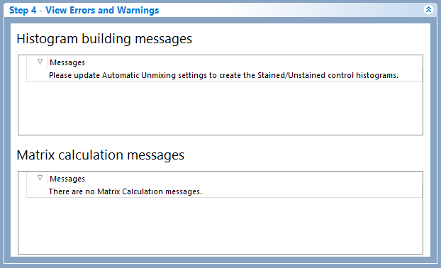
Figure 9.41 Step 4: View Errors and Warnings.
In the example below, the "CD3 BV711" label has been used twice. Step 4 is red colored and an the error appears in the Histogram building messages section (Figure 9.42)
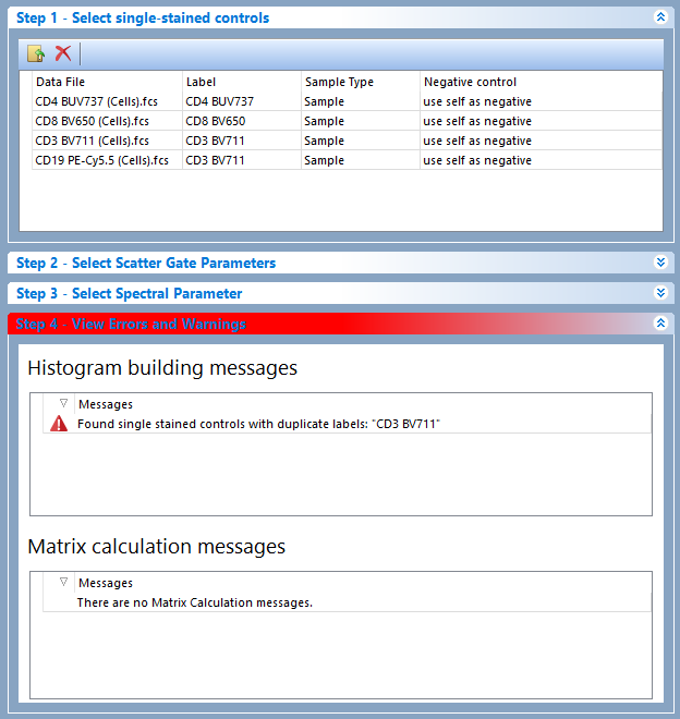
Figure 9.42 Step 4: View Errors and Warnings displaying a warning for duplicated label.
In the example below, the marker defining the "CD4 BUV737 stained" population was improperly placed causing the number of event in that population being zero. As a result, Step 4 is red colored and an error appears in the Matrix calculation messages section (Figure 9.43)
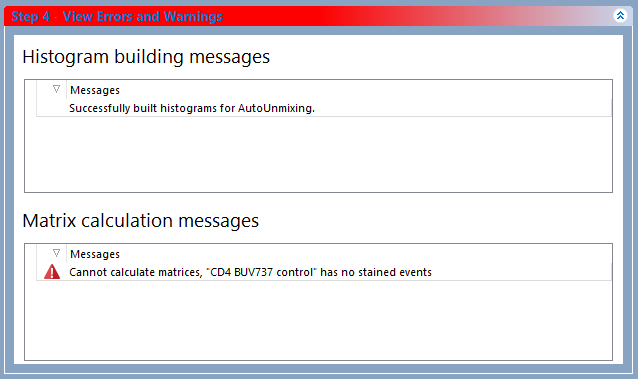
Figure 9.43 Step 4 displaying an error in the "Matrix calcualtion messages" section.
•Step 5 - Adjust parameters (optional).
Step 5 is useful when you would like to refine the populations that are used for calculating unmixing and to customize the automatically detected the brightest detectors in single stained controls.
Please see more on automatically detected the brightest detectors in the Spectral Unmixing Detection - Caveats and Troubleshooting for more information chapter.
Dragging and dropping new plots or gates in this section will allow you to override the automatic setup and use gates and plots of your choice.
For instance, if the Automatic Unmixing Setup does not make a good estimate of the population and if you would like to use a population from another gate or plot, Step 5 would be useful. Parameters may be adjusted or changed altogether by dragging and dropping a plot or gate onto the parameter for the Stained and Unstained columns. If a gate is dropped, the unmixing definition will be based on that gate, including its hierarchical position visible in the Gate View object. If a plot is dropped, the unmixing definition will be based on the Stained/Unstained population on that plot.
If you modify the detector using the dropdown menu, the pipeline automatically updates the virtual band pass steps to reflect the changes (Figure 9.44).
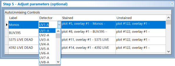
(Figure 9.44) The dropdown menu containing the list of detectors in Step 5 - Adjust parameters (optional)
Note: If you have adjusted a parameter after the matrix has been calculated it will automatically recalculate and apply the change.
Instructions for adjusting parameters using Spectrum Plots (Figure 9.45):
1. Click on any of the auto-generated spectrum plots you would like to use to .
2. In the ribbon, navigate to Gating→Create Gates→Current Gate and select No Gate from drop down menu. The spectrum plot will then be ungated.
3. Create a gate on the spectrum plot to identify the population/detector of interest.
4. Drag the gate and drop it on appropriate cell in the AutoUnmixing Controls table.
5. Release the mouse button.
6. The new gate and or plot will appear by name in the appropriate cell in the AutoUnmixing controls table of the Adjust parameters pane.
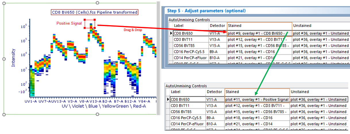
Figure 9.45 - To change a parameter or gate drag for the stained or unstained control, drag the gate or plot to the control you wish to change. The information in the AutoUnmixing Controls table will update accordingly.
•Step 6: Calculate matrices
In the final step you may choose to Calculate Matrices based on the Mean or Median depending on your preference for your data and experiment (Figure 9.46). Click on the radio button for either choice to apply your preference.
By default the Unmixing Matrix will be recalculated every time the gates used in the Unmixing wizard will be adjusted. To switch off said automatic update, simply uncheck the "Recalculate matrix automatically when something change".

Figure 9.46 - Step 6 of the Automatic Unmixing Setup wizard.
The calculated matrix will be visible in the Unmixing Matrix tab (Figure 9.47). Please also see the section on The Unmixing Window to learn how to rename, save, load, and delete specific end members of the matrix. Once the matrix is calculated, the matrix endmembers (i.e. the normalized spectra) will be automatically graphed in a scatter plot in the Visualized Mixing Matrix page.
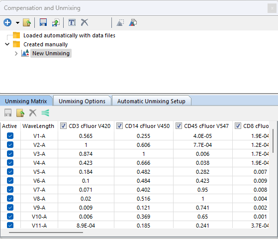
Figure 9.47 - An example unmixing matrix after completion of Automatic Unmixing.
